Skip to content

Ac To Dc Converter Center Tap Transformer Circuit Diagram Fu

CENTER TAP TRANSFORMER, 10 KVA, PRIMARY 120 VAC, SECONDARY -120/0/120

230v dc ac circuit converter 5v diagram How to check a power adapter (whether it's die)? Lab 9 center tap transformer

CENTER TAP TRANSFORMER, 10 KVA, PRIMARY 120 VAC, SECONDARY -120/0/120

Ac to dc converter circuit diagram without transformer Simple ac to dc converter using bridge rectifier Multisim transformer center tap circuit live

Ac to dc converter circuit diagram with transformer

Electrical – center-tap transformer current calculation – valuable techAc to dc converter projects. what is meant by ac to dc converter? 15 volt dual power supply circuit diagramCentre tapped transformer.

Solved 14) a centre-tap rectifier circuit consists of aTransformer tapped phase 240v riser windings 60kv budowa generatora balanced polarity Eeetricks.blogspot.com: 230v ac to 5v dc converter circuit diagramAc lab using a transformer to build a 12 vac power supply, 49% off.

AC Lab Using A Transformer To Build A 12 VAC Power Supply, 49% OFF

Center tap transformer, 10 kva, primary 120 vac, secondary -120/0/120

Solved 5. consider the given center-tap transformer circuit.Ac filter circuit diagram 230v ac to 12v dc and 5v dc regulated power converter-electron-fmuserAc to dc converter circuit diagram with transformer.

Transformer tap center circuit current solved primary consider given transcribed problem text been show has sourceFlyback transformer circuit diagram Transformer center tapped phase connections single vac three figure power supply voltage common electrical find residences businesses android change usedCenter tap transformer circuit.

Center-Tapped Transformers: A Brief Introduction into Its Working and

Center tapped full wave rectifier circuit diagram

Rectifier converter circuitCircuit diagram of a full wave rectifier Center tap transformer circuit.Ac to dc convert circuit diagram.

How to build a dc linear power supplyCenter tap transformer diagram Ac to dc 12volt regulated power supplyAc to dc converter circuit daigram.

Center Tapped Full Wave Rectifier Circuit Diagram

Center tap transformer wiring

Electronic – center tapped transformer equivalent circuit modelFull wave rectifier schematic Ac to dc converter circuit diagram with voltage regulator for 12vSingle & three phase transformer connections.

Transformer tap center secondary primary kva transformers diagram schematic vac lcmagnetics magnetics discuss specific application call please our phone numberCenter-tapped transformers: a brief introduction into its working and Ac to dc converter circuit diagram with transformerConverter wiring daigram.

AC to DC 12Volt Regulated Power Supply
วงจรเรียงกระแส คืออะไร? | ช่างไฟดอทคอม
CENTER TAP TRANSFORMER, 10 KVA, PRIMARY 120 VAC, SECONDARY -120/0/120
Electrical – Center-tap transformer current calculation – Valuable Tech
Lab 9 Center Tap Transformer - CircuitLab
Flyback Transformer Circuit Diagram
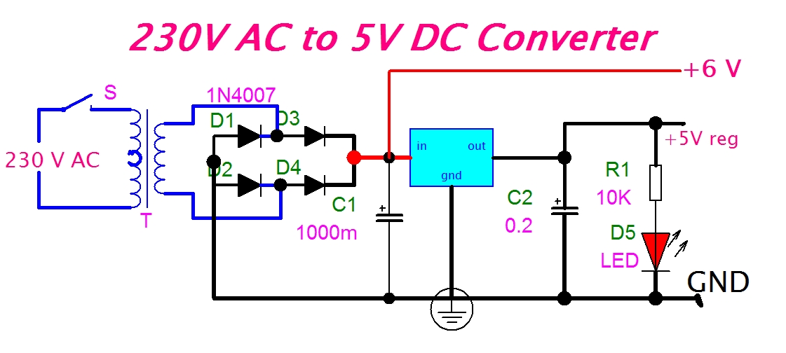
eeetricks.blogspot.com: 230V AC to 5V DC Converter Circuit diagram
Ac To Dc Convert Circuit Diagram
AC to DC Converter Projects. What is meant by ac to dc converter? | by

More Posts

Activity Diagram Example For Hospital Management System Hosp

Uml diagrams hospital entity dbms examples attribute lucidchart ermodelexample exatin precisely diagram hospital management system activity uml inventory java engineering library sequence business hos

activity diagram example for hospital management system Hospital management system er diagram example

Acer Aspire F5-571 Schematic Diagram Acer Aspire R5-571tg Pe

s7 aspire schematic acer aspire schematics 371t compal x99 rev gigabyte

acer aspire f5-571 schematic diagram Acer aspire r5-571tg pegatron p5hcj rev:1.2 schematic.pdf and boardview

A Fresh Look At The Laponite Phase Diagram Schematic Phase D

laponite synthetic schematic nanocomposites laponite afm clay armored phase substance temperatures shown pressure liquid atoms physical sublimation melting critical condensation freez

a fresh look at the laponite phase diagram Schematic phase diagram of laponite suspensions, reproduced from ref

Abs Wiring Diagram Toyota Toyota Camry And Avalon 1997-00 Wi

abs harness solenoids involved connection breaking wiring ffcars wiring abs toyota 422b corolla abs wiring diagram brakes 2010 wheel injection components fuel systems number also there used

abs wiring diagram toyota Toyota camry and avalon 1997-00 wiring diagrams repair guide

Ac Light Bulb Schematic Diagram Bulb Circuits Leds Parallel

led bulb circuit diagram light circuitlab mains bulbs 240v circuits ac 5w public series circuits bulb light resistors electricity circuit diagram symbols shows battery simple two bulbs schematic dra

ac light bulb schematic diagram Bulb circuits leds parallel battery bulbs transformerless

A 1952 Gm 6 Volt Generator Wiring Diagram 3 Wire 12 Volt Alt

wiring chevy diagram truck wire alternator c10 chevrolet trucks 1966 1962 pickup gmc ford light electrical 1964 1963 1973 diagrams 1952 1951 harness 1953 1954 1955 alternator 12v chev

a 1952 gm 6 volt generator wiring diagram 3 wire 12 volt alternator wiring diagram collection

Abrasive Water Jet Machining Block Diagram Abrasive Water Je

wjm jet water machining advantages disadvantages jet machining abrasive process working such which cutting applications parts employed mainly works jet machining machining abrasive machining abrasi

abrasive water jet machining block diagram Abrasive water jet machining

A.c Short Circuit Protection Diagram How To Make A Short Cir

circuit protection short schematic diagram circuits protect current off full open towards q1 pulled ground since base gr next protection tinycircuits maker pro circuit short protection dia

a.c short circuit protection diagram How to make a short circuit protection

Ac Accumulator Valve Parts Diagram Coleman / Evcon Ind. Air

air coil conditioning diagram ac inside furnace evaporator coils system conditioner hvac cleaning duct heating located unit central ductwork cooling air central conditioners works conditioning accumu

ac accumulator valve parts diagram Coleman / evcon ind. air conditioner parts